Measure to optimise.
Fundamentals of resistance spot welding, nugget quality and statistical control, and how to put it all into practice in Weldia.
Sections
Everything you need to weld and measure better.
How a spot weld forms
Joule's law, contact resistances, the weld cycle, the eight factors and the materials.
Process window and defects
Weldability lobe, expulsion, cold welds, gaps, shunting, LME and root cause analysis.
From measurement to SPC
Measurement sessions, weld spot management, I-MR charts, Cpl capability, alerts and opportunities.
By role
Choose your path.
Measurement technician
Runs measurement sessions on the shop floor.
Quality engineer
Follows SPC, alerts and capability.
Process engineer
Manages weld spots, parameters and guns; analyses opportunities.
Management and administration
Consults indicators and manages the organisation.
Improvement cycle
From opportunity to validation measurement.
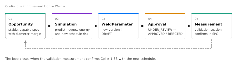
Weldia turns measurements into signals of stability, risk and gain. The goal is to close the loop between quality and process.
See opportunities02 Simulation → predict nugget and energy
03 WeldParameter → new DRAFT version
04 Approval → UNDER_REVIEW → APPROVED
05 Measurement → confirm Cpl ≥ 1.33
Getting started
How to use this wiki
The wiki is organised in three layers: the technical fundamentals, quality and defects, and use of the platform. Each technical concept points to the place in Weldia where it applies.
Structure
| Section | What for | Key pages |
|---|---|---|
| Fundamentals | Understand why a spot weld turns out well or badly | Principle, Cycle, Eight factors |
| Quality and defects | Diagnose and prevent problems | Process window, Common problems, Root cause |
| Weldia in practice | Use the platform day to day | Sessions, SPC Cockpit, Opportunities |
| Reference | Look up standards, terms and sources | ISO standards, Glossary, Frequently asked questions |
Conventions
Blue boxes link the concept to the screen, field or rule of the platform.
Amber boxes flag common mistakes or quality risks.
Green boxes summarise the recommendation to apply.
- Platform field names, statuses and rules appear in
monospace:NEEDS_REVIEW,CPL_BELOW_1_33. - Technical terms give common synonyms in brackets on first occurrence: expulsion (splash).
- The figures are illustrative: they show qualitative trends, not data from a real line.
Wiki shortcuts
| Key | Action |
|---|---|
| / | Go to search |
| ↑ ↓ Enter | Navigate the search results |
| Esc | Close the search or the menu |
Content source
The full technical content is in the file docs/wiki/conhecimento-soldadura-resistencia.en.md, and the figures in docs/wiki/images/en/. To update a figure, edit docs/wiki/tools/gerar_imagens.py and regenerate them.
Fundamentals
Principle of resistance welding
No arc and no filler material: a high current passes through the sheets clamped between two electrodes, and the electrical resistance locally melts the metal at the interface.
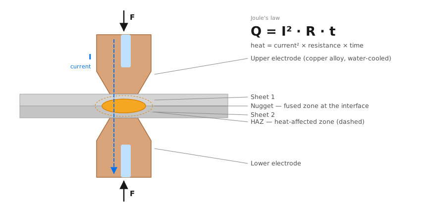
Joule's law
| Symbol | Meaning | Order of magnitude in car bodies |
|---|---|---|
I | Welding current (RMS) | 6 – 14 kA in steel; > 20 kA in aluminium |
R | Total resistance along the path | tens to hundreds of µΩ |
t | Current flow time | 100 – 600 ms |
- Current counts squared. +10 % current gives about +21 % heat. It is the most sensitive parameter.
- The heat has to originate at the interface. Design and parameters exist to concentrate the heat where the nugget is wanted.
- Heat is also lost. The electrodes are water-cooled; below a minimum current, more time does not form a weld.
The role of force
Force is applied before the current, to ensure contact; during it, to contain the molten metal; and after it, to forge the nugget as it solidifies.
Resistances in series
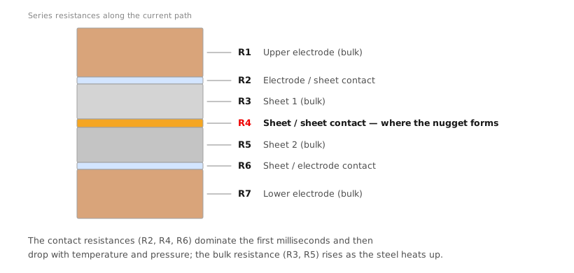
- Contact resistances (R2, R4, R6): dominate the first milliseconds and decrease with pressure and temperature.
- Material resistance (R3, R5): increases with temperature.
- Dynamic resistance: the R(t) curve that results from the two. It is the signal most used in real-time monitoring.
The result that is measured is the nugget diameter, recorded in each NuggetMeasurement and compared with the minimum diameter of the WeldSpot.
Fundamentals
Process families
Resistance welding processes differ in how they concentrate the heat: through the electrode, through the part or through an additional element.
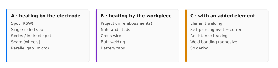
| Family | How the heat is concentrated | Examples |
|---|---|---|
| A, through the electrode | Shape of the electrode tip | Spot (RSW), single-sided, series, indirect, seam, parallel gap |
| B, through the part | Projections, embossments or the natural shape of the parts | Projection, nuts and studs, cross wire, butt, battery terminals |
| C, with an element | Element between the parts | Element welding, brazing, weld bonding, soldering |
Spot welding
It is the dominant process in car body assembly (body-in-white): a typical car has between 3,000 and 6,000 spot welds. The shape of the electrode tip defines the contact area and, with it, the size of the nugget.
Projection
The projection must concentrate the current without collapsing too quickly. As a rule, it goes on the part that has more difficulty heating up: the thicker one, if the materials are the same, or the one with lower resistivity, if they differ. Fast electrode follow-up is critical, because the projection collapses within milliseconds.
The platform focuses on family A, spot welding with robotic guns.
Fundamentals
Weld cycle and weld schedule
Each spot weld is made according to a weld schedule with well-defined phases. In Weldia, that schedule is stored and versioned in WeldParameter.
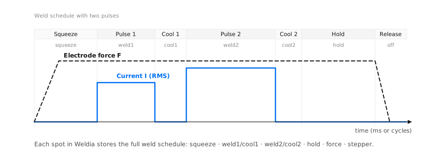
Phases
| Phase | Field | Function | Too short | Too long |
|---|---|---|---|---|
| Squeeze | squeeze | Close and stabilise the force | Initial expulsion | Lost cycle time |
| Pulse 1 | weld1 | Preheating, coating, gaps | — | Surface overheating |
| Cool 1 | cool1 | Pause between pulses | — | — |
| Pulse 2 | weld2 | Nugget growth | Cold weld | Expulsion, wear, indentation |
| Cool 2 | cool2 | Optional pause | — | — |
| Hold | hold | Solidify under force | Porosity, cracks, LME | Brittle nugget in hardenable steels |
| Force | force | Contact and forging | Expulsion | Less heat, indentation |
| Stepper | stepper | Compensate for electrode wear | Nugget shrinks | Expulsion at end of life |
On AC machines times are often given in mains cycles (1 cycle = 20 ms at 50 Hz). On MFDC they are given in ms. Check the unit before comparing weld schedules.
Current types
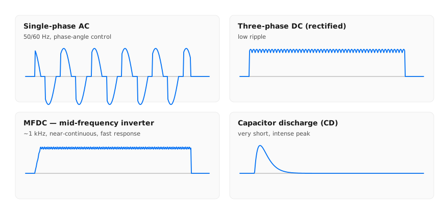
| Type | Characteristics | Use |
|---|---|---|
| Single-phase AC | 50/60 Hz, conduction angle | Older installations |
| Three-phase DC | Reduced ripple | Large guns, aluminium |
| MFDC | ~1 kHz, fast response, compact transformer | Standard in automotive robotics |
| Capacitor discharge | Short, intense peak | Micro-welding, conductors |
Fundamentals
The eight influencing factors
More than a hundred variables have been identified in the literature. In practice, they group into eight factors, and diagnosis works through them.
| # | Factor | Main effect | Typical sign |
|---|---|---|---|
| 1 | Current | Heat ∝ I²; the nugget grows quickly up to expulsion | Expulsion (high) · cold weld (low) |
| 2 | Time | Heat ∝ t; below the minimum current it is not enough | Electrode sticking with long times |
| 3 | Force | Defines the contact: too little → expulsion; too much → less heat | Indentation, initial expulsion |
| 4 | Contact resistance | Decides where the heat originates in the first cycles | Batch-to-batch variation, oil, oxides |
| 5 | Material | Resistivity generates heat; conductivity dissipates it | Change of supplier |
| 6 | Coatings | Zinc, AlSi: contact and electrode contamination | Accelerated wear |
| 7 | Geometry | Tip, thicknesses, no. of sheets, edge, pitch | Off-centre nugget, shunting |
| 8 | Machine | Current rise, inductive losses, stiffness, follow-up | Differences between "identical" guns |
Factors 1–3 → WeldParameter. Factors 5–7 → WeldSpot (sheet stack, thicknesses, minimum diameter) and GunConfiguration (electrode, tip dressing, maximum force). Factor 8 → robot and gun in the hierarchy.
Contact resistance in detail
All surfaces are rough at the microscopic scale. With more force, the asperities flatten, the real contact area increases and the resistance drops. With temperature, contaminants (water, oil) burn off and the metal softens, and the resistance also drops. Although it only dominates in the first cycles, it defines the initial heat distribution and, with it, where the nugget starts.
Machine characteristics
- Electrical: current rise time and inductive losses, which grow with the gun's throat opening and the steel inside the window.
- Mechanical: arm stiffness and electrode follow-up speed. Slow follow-up causes expulsion, especially in projection welding.
Fundamentals
Materials and weldability
Weldability is the ease with which a combination of materials and thicknesses produces good spot welds within a window wide enough for stable production.
General rule: metals with high resistivity and low thermal conductivity weld better.
| Material | Behaviour | Precautions |
|---|---|---|
| Low-carbon steel | Very good weldability | Reference |
| AHSS (DP, TRIP, MS, PHS) | Heats more; narrower window; expulsion at lower currents | Higher force, multi-pulse, suitable hold |
| Galvanised (GI, GA) | The zinc melts and alloys with the copper | More force and current; dress more often; LME risk |
| AlSi (hot stamping) | The coating becomes more resistive in the furnace | Adjust current; watch the projections |
| Aluminium | Low resistivity, high conductivity, oxide | Very high current, short time, cooling, cleaning |
| Copper | Generates little heat and dissipates it quickly | Projection, brazing, tungsten electrodes |
Heat balance
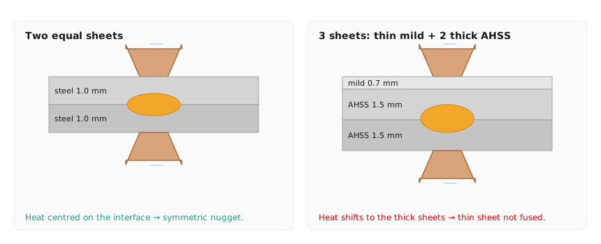
- The thicker sheet and the more resistive sheet heat up more.
- Thickness ratio (total ÷ thinnest): as a rule of thumb, up to 3:1 to 4:1.
- Three sheets with a thin, soft outer sheet is the most critical case in the car body.
- Solutions: electrodes of different diameters, pre-pulse, multi-pulse, ramped current, or revising the design.
Minimum diameter
| t (mm) | 0.7 | 1.0 | 1.2 | 1.5 | 2.0 |
|---|---|---|---|---|---|
| 4·√t (mm) | 3.3 | 4.0 | 4.4 | 4.9 | 5.7 |
| 5·√t (mm) | 4.2 | 5.0 | 5.5 | 6.1 | 7.1 |
The minimum diameter is an attribute of each WeldSpot and is the LSL used throughout SPC. When the material or the supplier changes, review weldability before assuming the old weld schedule.
Fundamentals
Electrodes and tip dressing
The electrode is the component that changes most during production. With wear, the face widens, the current density drops and the nugget shrinks.
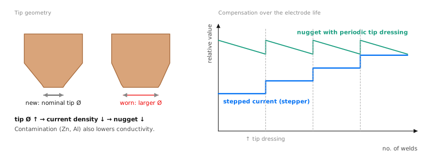
Mechanisms
- Geometric: the face widens (mushrooming), forms craters (pitting) or loses material. Typical with galvanised steel.
- Metallurgical: the copper alloys with zinc or aluminium, recrystallises and softens. With aluminium this happens very quickly.
Electrode life ends when the minimum diameter can no longer be reached. In the lobe, wear shifts the window towards higher currents.
Compensation
| Method | How it works | In Weldia |
|---|---|---|
| Stepped current | Raises the current in steps every N spot welds | stepper in the WeldParameter |
| Tip dressing | Restores the geometry and cleans the face every N spot welds | GunMillingProgram 241 / 242 / 250 |
| Adaptive control | Adjusts the current from the dynamic resistance | Future device integration |
A sawtooth measurement series (drops and recovers) synchronised with tip dressing is normal. A continuous decline with no recovery indicates failed tip dressing, insufficient stepper or poor cooling.
Standards
Cap geometry is in ISO 5821 (for example, F shapes with 16 and 20 mm faces, such as the references FF16A00 and FF20A00 in GunConfiguration). Electrode materials are in ISO 5182 (CuCr1Zr, CuCo2Be, …).
Quality and defects
Process window
The nugget is hidden between the sheets and cannot be inspected visually. Quality is ensured by working within a known parameter window.
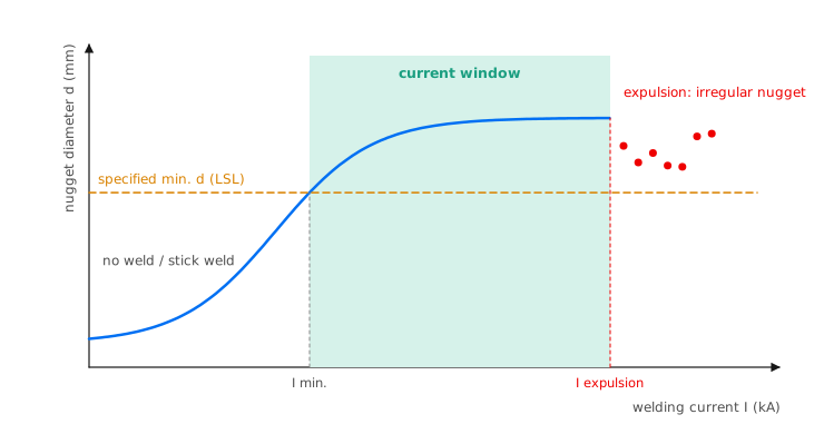
Growth curve
Only the current varies, with force and time fixed. It is useful when force and time are already defined.
Weldability lobe
It maps two variables, current × time or current × force, and gives a more complete view of the process (ISO 14327).
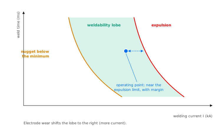
How to choose the working point
- Stay inside the lobe. Outside it there are cold welds or expulsions.
- Prefer the expulsion side, with margin. Wear and other disturbances reduce the nugget over time. Starting near the upper limit gives more headroom to the lower one.
- Keep a margin to expulsion (typically 0.5 – 1 kA in steel), and more if there are gaps or misalignments.
- Higher force widens the lobe, but shortens electrode life and increases indentation.
- Stronger steels have the expulsion limit at lower currents.
SPC shows when a weld spot leaves the window on the low side (mean falling, Cpl dropping). Opportunities show weld spots with margin to reduce time or energy without leaving it.
Quality and defects
Defects and failures
Defects fall into three classes, and the class already points to the likely cause.
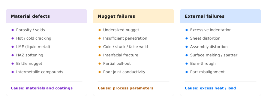
| Class | Dominant cause | Where to act |
|---|---|---|
| Material defects | Materials and coatings at critical temperature and stress | Choice of materials; hold and multi-pulse |
| Nugget failures | Parameter setting | Weld schedule optimisation |
| External failures | Excess heat or force | Reduce energy, adjust force and fixturing |
Acceptance criterion
In the peel test or the chisel test (ISO 10447), a good spot weld fails with full button pull-out (full plug). Interfacial fracture generally indicates an insufficient weld, although in ultra-high-strength steels it should be assessed case by case.
Recording a defect in Weldia
- Measure the diameter of the pulled-out button and enter it in the session task.
- If it is below the minimum, the platform asks for an explicit decision: keep
MEASUREDor change toNEEDS_REVIEW. - To flag for review in any case, use the R key.
- Saving creates a new revision and queues the SPC recalculation for the weld spot.
Quality and defects
Common problems in production
Cold weld, expulsion, gaps and misalignment: the most common causes, how to recognise them and how to reduce them.
Cold weld / stuck weld
No nugget of sufficient size forms, or it forms at only one of the interfaces. It is one of the most serious problems in multi-sheet stacks.
| Cause | Example | Action |
|---|---|---|
| Poor contact | Electrode poorly seated, gap | Ensure contact, close the gap during squeeze |
| Poor parameters | Low current, short time, large face | Optimise current/time/force; dress the tips |
| Heat balance | High ratio, different resistivities | Different electrodes, pre-pulse, multi-pulse |
Expulsion / spatter
Molten metal is ejected from the nugget. It causes defects, cosmetic problems, risks to operators, dirt on the line and wasted energy.
- Parameters: high current, long time, low force.
- Small contact: unevenly worn face, misaligned electrodes.
- Surface: dirt, oxides, anything that increases the surface resistance.
- Gap between sheets.
Frequent expulsions indicate a process too close to the upper limit of the window. Lowering the current blindly, however, pushes the process towards the lower limit: check the electrode and the gap first.
Gap between sheets
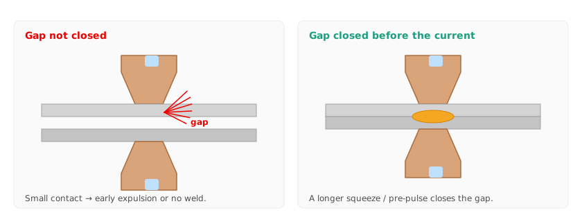
- It comes from stamping or fixturing tolerances.
- It shifts the expulsion limit to lower currents and narrows the lobe.
- Robust strategy: parameters in the zone common to the lobes of the expected gaps (0, 0.2, 0.5 mm…).
- Direct solutions: longer squeeze, more squeeze force, low-current pre-pulse.
Electrode misalignment
It results from assembly errors or from the elastic deflection of the gun: the electrodes end up tilted or with offset centres. The nugget becomes irregular and there are expulsions. Checking the gun's squareness is part of preventive maintenance.
Hot-stamped parts
22MnB5 parts with AlSi arrive with a transformed coating of higher resistance and with very high hardness. Changes in the furnace later show up as variations in welding. On projection nuts, the difference in hardness can make the projection collapse before the weld forms.
See also: Shunting effect · LME.
Quality and defects
Shunting effect
Part of the current is diverted through nearby spot welds that have already been made. The new spot weld receives less current and turns out smaller.
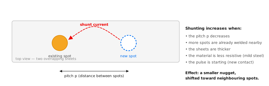
| Factor | Effect on shunting |
|---|---|
| Smaller pitch | ↑ strong, the most influential factor |
| More spot welds already made | ↑ cumulative along a row |
| Thicker sheets | ↑ less resistive lateral path |
| Mild steel | ↑ compared with high-strength steels |
| Start of the pulse | ↑ the new contact is still very resistive |
In a row of spot welds, the diameter reduction can accumulate to 20–30 % at the last spot weld, and the nuggets lean towards their neighbours. In a three-sheet combination, the interface with mild steel is the most affected.
Respect the minimum pitch, order the welding sequence and compensate the current of the spot welds in sequence.
Weld spots in the same cell with systematically smaller diameters in a dense zone (Drilldown and Equipment tabs) are shunting candidates. Compare with the sequenceNo and the X/Y/Z coordinates.
Quality and defects
Liquid metal embrittlement (LME)
Cracking of zinc-coated high-strength steels, when liquid zinc penetrates the grain boundaries under stress.
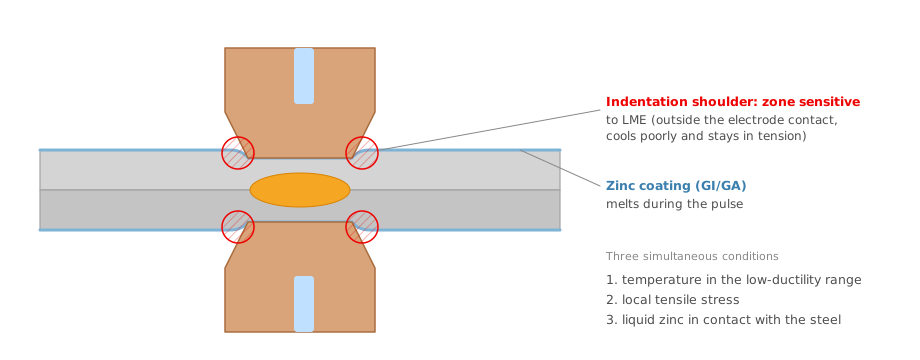
Three simultaneous conditions
- Temperature in the steel's low-ductility range.
- Local tensile stress, which increases with the heat input and with abrupt cooling.
- Liquid zinc in contact with the steel.
How to reduce it
- Avoid excess heat, especially near expulsion.
- Multi-pulse to reduce stress peaks, or a pre-pulse to push the zinc away.
- Electrodes without sharp edges in the contact zone.
- Sufficient hold for the zinc to solidify before the electrodes open.
Automotive industry studies (WorldAutoSteel) indicate that relevant LME cracks appear mainly when there are deviations from the correct parameter and assembly conditions. A process well centred in the window is the first line of defence.
Quality and defects
Root cause analysis
All root causes fit into three categories. Investigate in this order: a design problem cannot be solved with parameters.
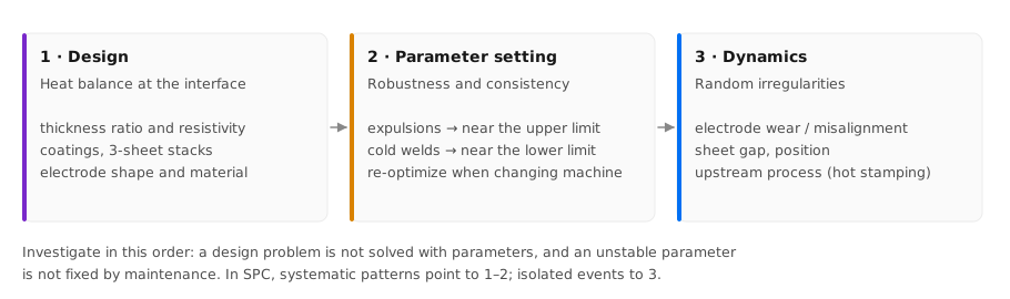
| Category | Key question | Typical SPC pattern |
|---|---|---|
| 1 · Design | Does the heat concentrate at the right interface? | Low Cpl from the start, on every gun with that combination |
| 2 · Parameter setting | Is the working point centred in the window? | Stable mean but close to the LSL; CPL_BELOW_1_33 |
| 3 · Dynamics | Did something change during production? | DOWNWARD_TREND_6, SAME_SIDE_BELOW_MEAN_8, BELOW_LCL |
Checklist when a weld spot goes into alert
- Confirm the measurement: method, operator, previous revision.
- Isolated or grouped? See the Equipment tab: weld spot, gun, robot, cell or tag.
- Grouped by gun: electrode, tip dressing, alignment, cooling.
- Grouped by product/tag: material batch, stamping, gaps.
- Isolated but persistent: parameter setting of that weld spot (window, shunting, edge).
- Record and act: if you change parameters, create a
DRAFTversion for approval and measure to validate.
Quick diagnosis table
| Symptom | Likely causes | First check |
|---|---|---|
| Diameter falling gradually | Electrode wear, insufficient stepper | Spot weld counter and last tip dressing |
| Sudden drop on one gun | Failed tip dressing, cap changed, cooling | Face condition and water flow |
| Drop across a whole product | Material batch, coating, stamping | Batch certificate, supplier |
| High scatter, good mean | Gaps, misalignment, unstable contact | Fixturing and gun squareness |
| Smaller spot welds in a dense zone | Shunting | Pitch and sequence |
| Expulsions and irregular diameter | High current, low force, gap | Approved vs. executed weld schedule |
Quality and defects
Quality beyond diameter
A spot weld can meet the minimum diameter and still be bad: with expulsion, excessive indentation, insufficient fusion or degraded metallurgy.
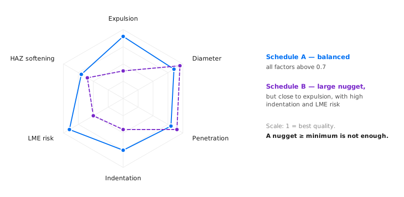
| Factor | What it measures | Why it matters |
|---|---|---|
| Expulsion | Stability | Defects, safety, energy |
| Diameter | Size of the fused zone | Strength |
| Penetration | Fusion into each sheet | Critical in 3-sheet stacks |
| Indentation | Surface deformation | Appearance, fatigue |
| LME risk | Susceptibility to cracking | Durability in AHSS |
| HAZ softening | Drop in hardness | Load-bearing capacity |
Hold and hardness
- Short hold → slow cooling → lower hardness → lower strength.
- Long hold → fast cooling → higher hardness → more brittle fracture.
- Optimal hold → balance between strength and ductility.
Destructive tests
| Test | Standard | Assesses |
|---|---|---|
| Peel / chisel | ISO 10447 | Button diameter and fracture mode |
| Tensile shear | ISO 14273 | Shear strength |
| Cross tension | ISO 14272 | Normal strength |
| Mechanised peel | ISO 14270 | Force-displacement curve |
| Torsion | ISO 17653 | Torsional strength |
Today the diameter is measured. The model already provides for indentationDepthMm, confidenceScore and the methods CAMERA, LASER_SCANNER, ULTRASOUND and AI_ASSISTED, for a multi-factor assessment.
Quality and defects
Energy and efficiency
Optimising is not only about getting acceptable spot welds: it is quality, stability and zero wasted energy, all at the same time.
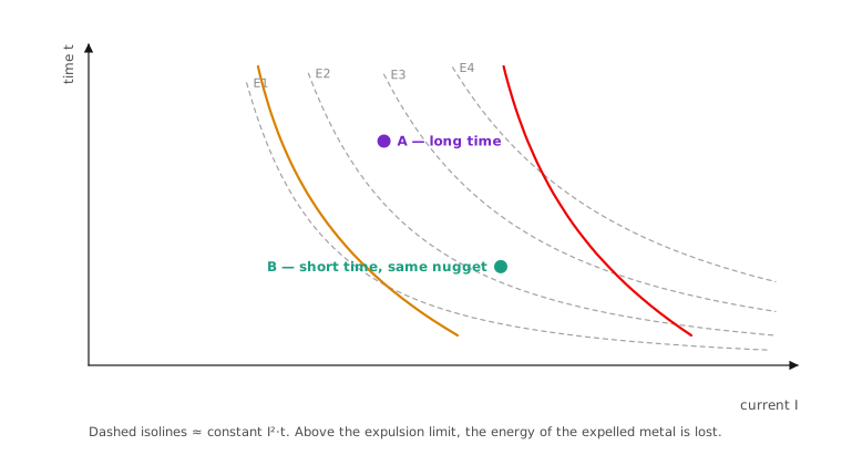
Two rules
- Avoiding expulsion also saves energy. The energy used to melt the expelled metal is lost, and the spot weld turns out worse.
- Within the lobe there are more economical weld schedules. Shorter times, with slightly higher current, lose less heat to the cooled electrodes.
Scale matters
| Quantity | Illustrative value |
|---|---|
| Energy saved per spot weld | 0.5 kJ |
| Spot welds per vehicle | 4,000 |
| Vehicles per year | 300,000 |
| Annual saving | 6 × 10¹¹ J ≈ 167 MWh |
A shorter weld time also reduces the cell's cycle time.
Weldia in practice
Overview and roles
Weldia brings together in a single workspace weld spot engineering, shop floor measurement, statistical control, optimisation and, soon, simulation and AI recommendation.
Modules
| Module | What it does | Status |
|---|---|---|
| Weld spot engineering | Registration, versioning, CSV | available |
| Sequential measurement | Nugget diameter weld spot by weld spot | available |
| SPC | Charts, capability, alerts, risk | available |
| Opportunities | Margin to reduce cycle time and energy | heuristic |
| Parameters and approval | Versioned weld schedules | read-only |
| Simulation | Predict the nugget from the parameters | demo |
| AI recommendation | Suggest parameters | planned |
Roles
| Role | Main use |
|---|---|
TECHNICIAN | Runs measurement sessions (fast, keyboard-driven flow) |
QUALITY_ENGINEER | Follows SPC, alerts, weld spots below the minimum and capability |
PROCESS_ENGINEER | Manages weld spots, parameters and guns; analyses opportunities |
ADMIN | Manages the organisation and the users |
VIEWER | Consultation (management, executives) |
Access requires login. Actions you cannot perform are hidden in the interface, and the server always validates the permission. All data is isolated per organisation.
Hierarchy
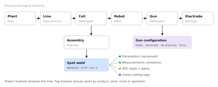
- Physical hierarchy (Project Explorer): plant → line → cell → robot → gun.
- Tags (Tag Explorer): cross-cutting groupings by product, zone, inspection route, operation or campaign.
Weldia in practice
The application
One route per flow, with a sidebar, a top bar with the scope, a command palette (Ctrl + K) and an inspector docked on the right.
Sections
| Route | What for |
|---|---|
Home (/) | Starting point, by profile |
Measure (/measure) | Rounds; a round opens in focus mode at /measure/<code> |
Quality (/quality) | Alert inbox, weld spots, overview; SPC detail of each weld spot |
Optimise (/optimize) | Cycle time and energy reduction opportunities |
Changes (/changes) | Parameter versions in review, validation and history |
Spots (/spots) | Catalogue, CSV import, orphans |
Settings (/settings) | Appearance, account and administration |
Simulation (/simulation) | Result of the latest simulation |
The scope (machines and tags) is chosen at the top and kept in the address, as are the filters and the inspector: a link reproduces the screen. The inspector shows the weld spot detail, the parameter set and the gun configuration. Old /workspace links redirect to the equivalent route.
Weldia in practice
Measurement sessions
A flow designed for the technician: fast, keyboard-driven and never overwriting history.
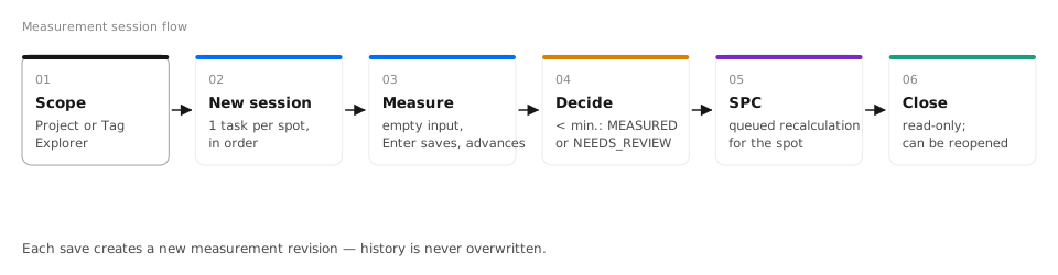
Step by step
- Select the scope (machines and tags) in the top bar and see the preview with the number of weld spots.
- New round (in
/measure) creates the session and one task per weld spot, in order. It can include several assemblies. - Measure weld spot by weld spot. The field starts empty; the last previous measurement appears separately, so as not to influence the reading.
- Choose the source: manual, test device or future Weldia device.
- Below the minimum, decide explicitly: keep
MEASUREDor change toNEEDS_REVIEW. - Each save creates a new revision of the measurement and queues the SPC recalculation for the weld spot.
- Close the session at the end. A closed session opens read-only; it can be reopened (resumes at the first pending task), archived and restored.
Keyboard shortcuts
| Key | Action |
|---|---|
| Enter | Save and advance |
| Ctrl + S | Save |
| ← → | Previous / next task |
| Esc | Leave the field / navigate |
| R | Flag for review |
| Skip button | Skip the task (no shortcut, on purpose) |
Always measure in the proposed order and do not skip tasks without a reason. The order helps detect sequence effects, such as shunting, and skipped tasks leave gaps in the control charts.
Correcting a measurement does not delete the previous one: it creates a new revision. SPC uses the most recent revision of each task.
Weldia in practice
Weld spot management
In /spots you create, edit, import (/spots/import) and export weld spots, always with revision history.
Create and edit
Each weld spot has a hierarchy, gun, sheet stack, X/Y/Z coordinates, minimum diameter and tags. Each change generates a WeldSpotRevision with the reason, which is mandatory.
Import CSV
- Download the CSV template to make sure the columns are right.
- Import the file. Operations are applied row by row, with staging.
- Rows without a match are left as orphans.
- In the orphan queue, link each row to an existing weld spot or ignore it.
Export
CSV export returns the filtered weld spots. The revision history of each weld spot can be consulted in the weld spot detail.
Change the minimum diameter only with technical justification (thickness, standard, customer). It is the SPC LSL: changing it changes the capability of the weld spot's entire history.
Weldia in practice
Parameters and guns
The weld schedule of each weld spot and the configuration of each gun are versioned, so that it is always known with which settings each measurement was made.
WeldParameter
Complete weld schedule per weld spot: squeeze, weld1/cool1, weld2/cool2, hold, force and stepper. See Weld cycle.
Approval statuses
| Status | Meaning |
|---|---|
| DRAFT | Proposal being edited |
| UNDER_REVIEW | Under review |
| APPROVED | Approved for production |
| REJECTED | Rejected |
| ARCHIVED | Replaced by a more recent version |
GunConfiguration
- Fluids: water (electrode cooling) and air.
- Electrode: cap type (e.g.
FF16A00,FF20A00). See Electrodes and tip dressing. - Tip dressing: programs
241,242and250, with cutter and frequency. - Maximum force of the gun.
Parameters are currently read-only. Editing and the approval flow are the next step of the improvement cycle.
Weldia in practice
SPC Cockpit
The nugget diameter only has a lower limit. That is why Weldia uses individual value charts and lower one-sided capability.
Tabs
| Tab | Use |
|---|---|
| Summary | KPIs and automatic insights for management |
| SPC | List of weld spots with status, Cpl, risk and alerts; chart for each weld spot |
| Opportunities | Weld spots with margin to reduce cycle time and energy |
| Equipment | KPIs by line, cell, robot, gun and tag |
| Drilldown | Detail of a weld spot or group |
You can filter by line, cell, robot, gun, tag, severity and statuses, and sort by priority, Cpl, risk, rejection or date. Bulk recalculation redoes the SPC for an entire scope.
Official series
- The latest revision of each
MEASUREDtask is included, ordered by measurement date. - The calculations use the last 50 samples of each weld spot.
- A measurement can be excluded with a reason (for example, a proven reading error). It stays visible in Drilldown but is left out of the calculations, and the exclusion is audited.
- Any change (new measurement, revision, exclusion) queues the recalculation for the weld spot.
Exclude only measurements that are proven to be wrong. Excluding "inconvenient" low values hides the problem and inflates the Cpl.
I-MR chart
| Element | Formula |
|---|---|
| Centre line | CL = mean |
| Moving range | MRᵢ = |xᵢ − xᵢ₋₁|, MR̄ = mean(MR) |
| Short-term σ | σ_within = MR̄ / 1.128 |
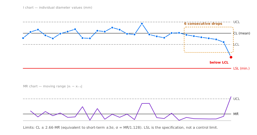
| Control limits | CL ± 2.66·MR̄ (≈ ±3σ_within) |
| Overall σ | sample standard deviation (n − 1) |
The UCL/LCL say what the process does; the LSL says what the customer requires. A weld spot can be within the control limits and below the LSL.
Capability
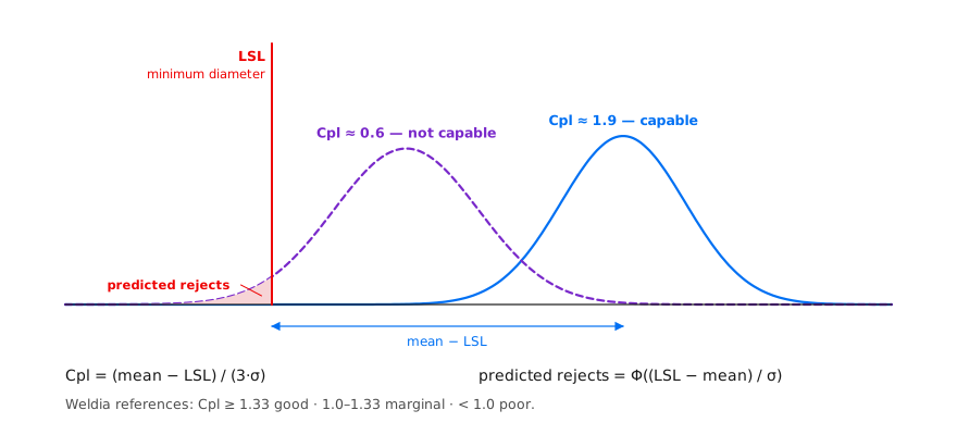
Ppl = (mean − LSL) / (3 · σ_overall)
predicted rejection = Φ((LSL − mean) / σ_overall)
| Cpl | Status | Reading |
|---|---|---|
| ≥ 1.33 and stable | GOOD | Capable, with margin |
| 1.0 – 1.33 | MARGINAL | Capable, without margin |
| < 1.0 | POOR | Not capable |
| < 10 samples | UNKNOWN | Insufficient data |
The process status is INSUFFICIENT_DATA (fewer than 10 samples), STABLE or UNSTABLE. See Alert rules and risk score.
Weldia in practice
Alert rules and risk score
The rules follow the classic Western Electric and Nelson logic, adapted to the lower side, which is the only one that represents a quality risk.
Rules
| Code | Rule | Severity | Likely cause |
|---|---|---|---|
BELOW_LSL | Measurement below the minimum | CRITICAL | Real defect |
PREDICTED_LOWER_REJECT_CRITICAL | Predicted rejection ≥ 3 % | CRITICAL | Poorly centred or scattered |
PREDICTED_LOWER_REJECT_WARNING | Predicted rejection ≥ 1 % | WARNING | Same, at an early stage |
CPL_BELOW_1_0 | Cpl < 1.0 | CRITICAL | Parameter setting or design |
CPL_BELOW_1_33 | Cpl < 1.33 | WARNING | No margin |
DOWNWARD_TREND_6 | 6 consecutive decreases | WARNING | Wear, drift |
SAME_SIDE_BELOW_MEAN_8 | 8 in a row below the mean | WARNING | Level shift |
LOWER_2_OF_3_2SIGMA | 2 of 3 below −2σ | WARNING | Imminent shift |
BELOW_LCL | Below the LCL | WARNING | Special cause |
ABOVE_UCL | Above the UCL | INFO | Change (opportunity or expulsion) |
Alerts have an OPEN → RESOLVED life cycle and are synchronised on every recalculation: an alert whose condition no longer holds is resolved automatically.
Risk score
Each weld spot receives a score from 0 to 100 to rank priorities.
| Component | Weight |
|---|---|
| Maximum severity of open alerts | 40 % |
| Cpl shortfall against 1.33 | 25 % |
| Predicted rejection (saturated at 5 %) | 20 % |
| Trend (series rules and LCL) | 15 % |
Deal with CRITICAL alerts first, then sort by risk score. For each alert, follow the root cause checklist.
Weldia in practice
Cycle time and energy opportunities
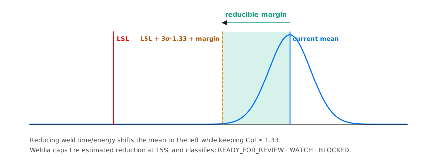
Stable, capable weld spots, with a nugget well above what is needed, can be welded with less time and less energy.
How it is calculated
- Only stable, capable weld spots are included (Cpl ≥ 1.33).
- Safety threshold =
LSL + 3σ·1.33 + margin. - Reducible margin = mean − threshold.
- Conversion into an estimated reduction in weld time (maximum 15 %) and in energy.
- Classification with an opportunity score and a confidence score.
| Class | Meaning |
|---|---|
| READY_FOR_REVIEW | Ready to propose a new weld schedule |
| WATCH | Promising, but with insufficient data or margin |
| BLOCKED | Do not touch: unstable, not capable or with alerts |
The estimate uses empirical constants and is not yet validated. An opportunity is a hypothesis: confirm it with a validation measurement before approving the new weld schedule.
Closing the loop
Weldia in practice
Simulation and digital twin
Simulation predicts the nugget before welding. The digital twin links that prediction to real production data.
Numerical simulation
It solves the electrical, thermal, mechanical and metallurgical problems together, usually with the finite element method, which handles large deformations and changing contacts well.
| Inputs | Outputs |
|---|---|
| Geometry and materials of the sheets, coatings and electrodes | Temperature, formation and diameter of the nugget |
| Force, current and times | Expulsion limit, indentation |
| Mesh and time step | Stresses, hardness, defect risk |
Run a mesh convergence study, use a time step below one millisecond in the current phases and always validate with a few physical tests.
Digital twin
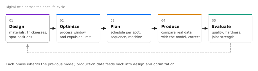
Each phase inherits the model from the previous one and adds data: from the generic machine at design time to the real measurements in production. The leap from "reacting to the defect" to "preventing the defect" is made by linking simulation to production data, and that is where SPC and AI come in.
In Weldia, today
- A simulation job queues a calculation and shows the predicted nugget, the energy, the cycle time and the risk.
- The current calculation is a linear demonstration formula. An adapter for an external simulation engine is planned.
- The platform already covers produce and evaluate (measurements, SPC, opportunities).
Reference
ISO standards
The standards most used in resistance welding, grouped by topic. Check the current edition in the ISO catalogue.
Processes
| Standard | Topic |
|---|---|
| ISO 17677-1 | Vocabulary: spot, projection and seam welding |
| ISO 15609-5 | Welding procedure specification (WPS) |
| ISO 14373 | Spot welding of low-carbon steels |
| ISO 18595 | Spot welding of aluminium |
| ISO 14327 | Weldability lobe |
| ISO 18278-1/-2/-3 | Weldability |
| ISO 15613 · ISO 15614-12 | Procedure qualification |
| ISO 14554-1/-2 | Quality requirements |
Equipment and electrodes
| Standard | Topic |
|---|---|
| ISO 669 | Mechanical and electrical requirements for the equipment |
| ISO 5182 | Electrode materials |
| ISO 5821 | Electrode caps |
| ISO 17657-5 | Verification of current measurement |
Tests
| Standard | Test |
|---|---|
| ISO 10447 | Peel and chisel |
| ISO 14273 | Tensile shear |
| ISO 14272 | Cross tension |
| ISO 14270 | Mechanised peel |
| ISO 17653 | Torsion |
Statistics
| Standard | Topic |
|---|---|
| ISO 7870-2 | Shewhart control charts |
| ISO 22514-2 | Capability of time-dependent processes |
Reference
Glossary
Terms in English, as they appear on the machines, in the standards and in the interface, with the Portuguese equivalent.
| English | Português | Definition |
|---|---|---|
| Resistance spot welding | Soldadura por pontos | Joining of sheets by localised fusion between two electrodes |
| Weld nugget | Nugget | Fused and solidified zone at the interface |
| HAZ | ZTA | Base metal altered by heat, without melting |
| Electrode / cap | Elétrodo / capa | Copper part that carries the current and applies the force |
| Welding gun | Pinça | Tool with arms, electrodes and transformer |
| Tip dressing | Fresagem | Restoring the geometry of the electrode face |
| Stepper | Corrente escalonada | Programmed increase of the current with wear |
| Squeeze | Aperto | Closing before the current |
| Weld pulse | Impulso | Period with current |
| Cool | Arrefecimento | Pause without current between pulses |
| Hold | Manutenção | Force held during solidification |
| Expulsion / splash | Expulsão | Ejected molten metal |
| Cold / false / stick weld | Ponto frio / falso | Spot weld without sufficient fusion |
| Indentation | Indentação | Depression left by the electrode |
| Shunting | Shunt | Current diverted through neighbouring spot welds |
| Gap / poor fit-up | Folga | Separation between sheets |
| Liquid metal embrittlement | LME | Cracking caused by liquid zinc |
| Weldability lobe | Lóbulo | Parameter region with acceptable spot welds |
| Weld growth curve | Curva de crescimento | Diameter as a function of current |
| Dynamic resistance | Resistência dinâmica | Evolution of R during the spot weld |
| Full plug | Arrancamento total | Fracture with the whole button pulled out |
| Interfacial fracture | Rotura interfacial | Fracture through the nugget interface |
| Advanced high-strength steel | AHSS | Advanced high-strength steels |
| Galvanised / galvannealed | GI / GA | Zinc / zinc-iron coatings |
| Lower specification limit | LSL | Specified minimum diameter |
| Control limits | LCL / UCL | Statistical control limits |
| Lower capability index | Cpl / Ppl | Lower one-sided capability |
| Digital twin | Gémeo digital | Virtual model linked to real data |
Reference
Frequently asked questions
Common questions from people starting to use Weldia.
Why does the measurement field start empty?
To avoid anchoring bias: if the previous value were in the field, it would be easier to confirm it than to measure. The last measurement appears separately, only as a reference.
Why is there only a lower limit (LSL)?
A larger nugget is not a defect in itself. The practical upper limit is expulsion, which is a process phenomenon and not a diameter specification. That is why capability is one-sided (Cpl).
How many measurements are needed to see the capability?
At least 10 per weld spot. Below that, the status is INSUFFICIENT_DATA and the capability UNKNOWN. With 20–30 measurements the estimate becomes considerably more stable.
A weld spot is within the control limits but below the minimum. How is that possible?
The control limits describe the natural variation of the process; the LSL is the requirement. A stable but poorly centred process stays within the control limits and still produces spot welds below the minimum. It is a parameter-setting case (see root cause).
I made a mistake in a measurement. Have I lost the history?
No. Each save creates a new revision; the previous one is kept. SPC uses the most recent revision. If the error can no longer be corrected in the session, an engineer can exclude the measurement from SPC, with a reason, in Drilldown.
What should I do with a READY_FOR_REVIEW opportunity?
Treat it as a hypothesis: propose a new weld schedule in DRAFT, submit it for approval and validate it with a measurement session before rolling it out.
The diameter falls and rises in a sawtooth pattern. Is that a problem?
If it coincides with tip dressing, it is the expected behaviour of electrode wear. Be concerned if the recovery stops happening or if the minimum of each tooth falls over time.
Reference
External references
Recommended public bibliography for going deeper into the topics of this wiki.
Resistance welding
- Zhang, H.; Senkara, J. Resistance Welding: Fundamentals and Applications, 2nd ed., CRC Press, 2011.
- American Welding Society. Welding Handbook, Vol. 3, chapter Resistance Spot Welding.
- AWS C1.1. Recommended Practices for Resistance Welding.
- AWS D8.9M. Test Methods for Evaluating the Resistance Spot Welding Behavior of Automotive Sheet Steel Materials.
- WorldAutoSteel. AHSS Application Guidelines: ahssinsights.org.
- ISO/TC 44/SC 6. Resistance welding and allied mechanical joining: iso.org.
Statistics and quality
- Montgomery, D. C. Introduction to Statistical Quality Control, 8th ed., Wiley, 2019.
- AIAG. Statistical Process Control (SPC) Reference Manual, 2nd ed., 2005.
- NIST/SEMATECH. e-Handbook of Statistical Methods: itl.nist.gov/div898/handbook.
- Western Electric. Statistical Quality Control Handbook, 1956.
- Nelson, L. S. "The Shewhart Control Chart: Tests for Special Causes", Journal of Quality Technology, 16(4), 1984.
Simulation and digital twin
- Grieves, M.; Vickers, J. "Digital Twin: Mitigating Unpredictable, Undesirable Emergent Behavior in Complex Systems", Springer, 2017.